
VDL Compositor Application
- Introduction
- User Interface Controls
- Composing a New Model
- Editing a Model
- Viewing and Editing Model Structure
- Creating a Tool Set
- Creating and Editing Rules
1. Introduction
The Visualization Description Language (VDL) is an XML tag-based language for describing interactive visualizations. VDL visualizations or models are implementation language independent visual descriptions of data.
This document describes the VDL Compositor Application. The VDL Compositor is a prototype application that enables users to:
- create new VDL models by dragging and dropping visual presentations, layouts and filters;
- edit existing VDL models by changing properties and dragging and dropping visual presentations, layouts and filters;
- create and edit rules;
- composite existing VDL models with layouts; and
- create an edit tool sets by dragging and dropping tools.
This document describes the facilities provided by the VDL Compositor and how to use them. Section 2 describes the user interface controls. The remaining sections describe the following topics:
- composing a new model;
- editing a model;
- viewing and editing model structure;
- creating a tool set; and
- creating and editing rules.
2. User Interface Controls
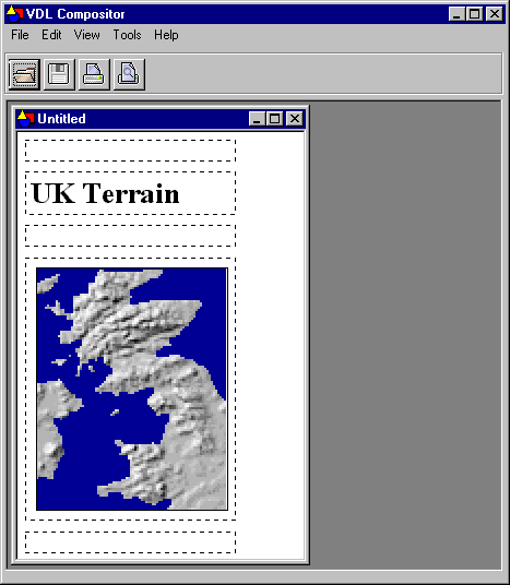
Figure 2.1 shows the VDL Compositor application with a VDL model displayed in a model window. The main window has three parts:
- menu bar;
- tool bar; and
- model windows.
These parts are described in the following sections.
Figure 2.1 – The VDL Compositor application.
2.1 The Menus
The VDL Compositor has the following menus:
- file menu
- edit menu
- view menu
- tools menu
- help menu
The File Menu
The File menu is shown in figure 2.2.
Figure 2.2 – The File menu.
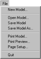
- New Model
- Create a new VDL model in an empty model window.
- Open Model
- Open a VDL Model. Models can also be opened by dragging the filename of a VDL model onto the main window of the VDL Compositor.
- Save Model
- Save the model in the currently selected window.
- Save Model As
- Save the model in the currently selected window with a new file name.
- Print Model
- Print the model in the currently selected window.
- Print Preview
- Preview what will be printed.
- Page Setup
- Change the current printer settings.
- Quit
- Exit the VDL Compositor application.
The Edit Menu
The Edit menu is shown in figure 2.3.
Figure 2.3 – The Edit menu.
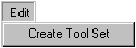
- Create Tool Set
- Open a new tool set window.
The View Menu
The View menu is shown in figure 2.4.
Figure 2.4 – The View menu.
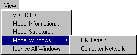
- VDL DTD
- Display the XML Document Type Definition (DTD) for VDL.
- Model Information
- Display the model information for all of the models currently opened in the VDL Compositor.
- Model Structure
- Display the Model Structure window.
- Model Windows
- Select a model name from this menu to bring the window containing the model to the front.
- Iconise All Windows
- Iconise all the model windows.
The Tools Menu
The Tools menu is shown in figure 2.5.
Figure 2.5 – The Tools menu.
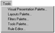
- Visual Presentation Palette
- Select this option to display the Visual Presentation Palette.
- Layouts Palette
- Select this option to display the Layouts Palette.
- Filters Palette
- Select this option to display the Filters Palette.
- Tools Palette
- Select this option to display the Tools Palette.
- Rule Editor
- Select this option to display the Rule Editor.
The Help Menu
The Help menu is shown in figure 2.6.
Figure 2.6 – The Help menu.

- About
- Display information about the VDL Compositor application.
- Topics
- Display a list of help topics available for the VDL Compositor application.
2.2 The Toolbar
Figure 2.7 shows the VDL Compositor toolbar. The icons on the toolbar provide file operations that are also available from the File menu.
 Open
Open- Open a VDL model. Equivalent to File>Open.
 Save
Save- Save the model in the currently selected window. Equivalent to File>Save.
 Print
Print- Print the model in the currently selected window. Equivalent to File>Print.
 Print Preview
- Preview what will be printed. Equivalent to File>Print Preview.
Figure 2.7 – The toolbar.

2.3 The Palettes
The VDL Compositor application has four palettes that contain icons representing VDL objects that can be dragged onto a model window to compose a model.
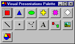
The Visual Presentation Palette
The Visual Presentation Palette is displayed with Tools>Visual Presentation Palette and is shown in figure 2.8. The Visual Presentation Palette provides the following VDL visual presentation icons that can be dragged and dropped onto a VDL model window.
 |
Rectangle |  |
Line |
 |
Triangle |  |
Point |
 |
Ellipse |  |
Bezier Curve |
 |
Plus |  |
String |
 |
Cross |  |
Link |
 |
Diamond |  |
Image |
 |
VDL Model |
Figure 2.8 – The Visual Presentation Palette.
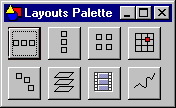
The Layouts Palette
The Layouts Palette is displayed with Tools>Layouts Palette and is shown in figure 2.9. The Layouts Palette provides the following VDL layout icons that can be dragged and dropped onto a VDL model window.
 |
Row |  |
Arc |
 |
Column |  |
Overlay |
 |
Grid |  |
Sequence |
 |
Position |  |
Path |
Figure 2.9 – The Layouts Palette.
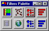
The Filters Palette
The Filters Palette is displayed with Tools>Filters Palette and is shown in figure 2.10. The Filters Palette provides the following VDL filter icons that can be dragged and dropped onto a VDL model window.
 |
Space Filler Filter |  |
Cache Matrix Chart |
 |
Scatter Plot Filter |  |
Cache Bar Chart Filter |
 |
Sequence Model Filter |  |
Document Matrix Chart Filter |
 |
Geographical Names Information Service (GNIS) Filter |  |
Document Bar Chart Filter |
Figure 2.10 – The Filters Palette.
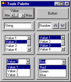
The Tools Palette
The Tools Palette is displayed with Tools>Tools Palette and is shown in figure 2.11. The Tools Palette provides the following VDL tool icons that can be dragged and dropped onto a VDL model window.
 |
Range Input |  |
Button |
 |
String Input |  |
Number Input |
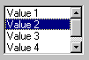 |
Single Selection List | 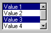 |
Multiple Selection List |
 |
Combo Selection | 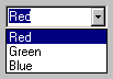 |
Color Selector |
Figure 2.11 – The Tools Palette.
3. Composing a New Model
New VDL models can be created by composing VDL models and objects with a layout. A new model is created with File>New Model. A new model can be created by first adding a layout to a new model. A layout is added to a new model by dragging a layout icon from the Layouts Palette onto the model window.
Figure 3.1a shows the dashed outlines of a column layout template. The large dashed rectangle is a cell in the layout onto which VDL objects such as visual presentations and layouts can be dragged and dropped. VDL objects can be inserted between the cells by dragging them onto the insertion points represented by the thin dashed rectangles. There is an insertion point on both sides of a layout cell to enable new objects to be inserted before and after the cell.
Figure 3.1 – Adding a column layout to a new VDL model.
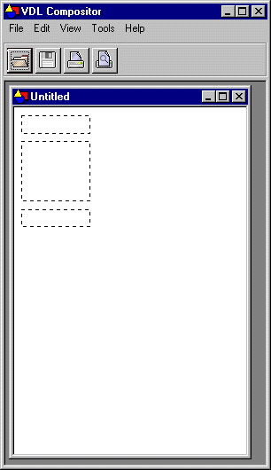
(a) The column layout template
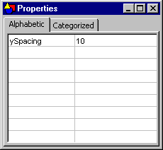
(b) Column layout properties
All VDL objects have properties [VDL 1] and figure 3.1b shows the Properties window displaying the single property, ySpacing, of the column layout. The value of a property can be changed by editing the value displayed in the Properties window.
The following VDL code will be produced for the model displayed in figure 3.1a.
<model>
   <group>
      <presentation>
         <layout type="column" ySpacing="10">
      </presentation>
   </group>
</model>
Figure 3.2a shows the drag and drop feedback displayed when a VDL object is dragged over an insertion point. Figure 3.2b shows the drag and drop feedback when a VDL object is dragged over a layout cell.
Figure 3.2 – The drag and drop insertion feedback.
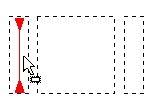
(a) The insertion point feedback
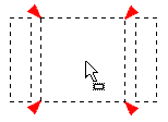
(b) The layout cell insertion feedback
Figure 3.3a shows the model after a string visual presentation has been dragged from the Visual Presentation Palette onto the layout cell. After editing the value property of the string visual presentation in the Properties window (figure 3.3b) the icon is replaced with the text UK Terrain (figure 3.3c). The following VDL code will be produced for the model displayed in figure 3.3c.
<model>
   <group>
      <presentation>
         <layout type="column" ySpacing="10">
      </presentation>
      <unit>
         <presentation>
            <visual type="string" colour="black" fontSize="20"
                    fontStyle="plain" value="UK Terrain" />
         </presentation>
      </unit>
   </group>
</model>
Figure 3.3 – Adding a string visual presentation to the new VDL model.
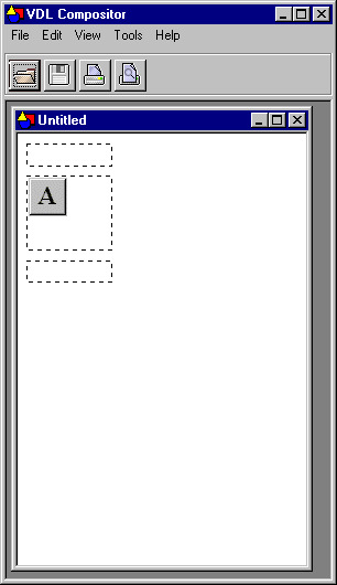
(a) Adding the string visual presentation to a column template
(b) Updating the value of the string visual presentation with the Properties window
(c) The updated string visual presentation
Figure 3.4a shows the model after a VDL model has been dragged from the Visual Presentation Palette onto the bottom insertion point of the layout. After entering the filename of the UK Terrain model the main group of the UK Terrain model is copied into the new model. The properties of the UK Terrain model are displayed in the Properties window shown in figure 3.4b.
Figure 3.4 – Adding an existing VDL model to the new VDL model.
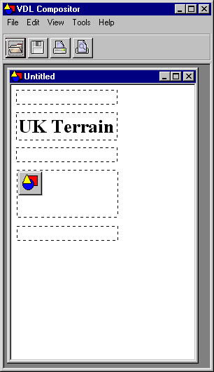
(a) Adding a VDL model visual presentation to a column layout
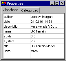
(b) Viewing the VDL model visual presentation with the Properties window
Figure 3.5a shows the UK Terrain model after it has been copied into the new model. Figure 3.5b shows the new model as it would look in the VDL Browser without any composition lines. The following is a sample of the VDL code that will be produced for the model displayed in figure 3.5.
<model>
   <group>
      <presentation>
         <layout type="column" ySpacing="10">
      </presentation>
      <unit>
         <presentation>
            <visual type="string" colour="black" fontSize="20"
                    fontStyle="plain" value="UK Terrain" />
         </presentation>
      </unit>
      <group name="UK Terrain">
         <presentation>
            <layout type="grid" rows="111" columns="87" />
         </presentation>
         ...
      </group>
   </group>
</model>
Figure 3.5 – The new VDL model.
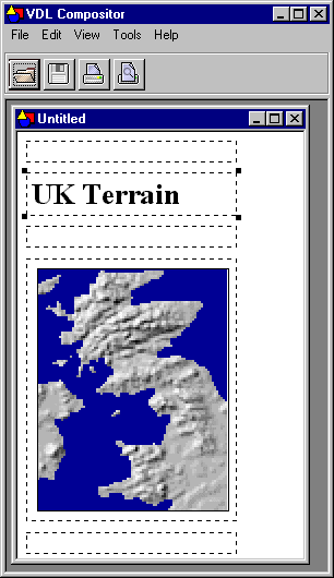
(a)
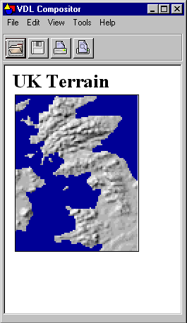
(b)
4. Editing a Model
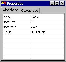
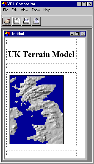
The properties of any VDL object such as a visual presentation or a layout can be changed by editing a value in the Properties window. Figure 4.1a shows the new model after the string visual presentation UK Terrain has been selected by clicking on it. The properties of the string visual presentation are shown in figure 4.1b. Figure 4.2a shows the new model after the title has been changed from UK Terrain to UK Terrain Model. Figure 4.2b shows the new model as it would look in the VDL Browser without any composition lines.
Figure 4.1 – Editing the value of a property.
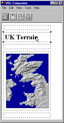
(a)
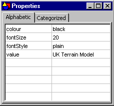
(b)
Figure 4.2 – The edited model.
(a)
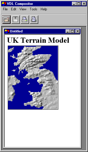
(b)
5. Viewing and Editing Model Structure
The View Structure window enables the structure of a VDL model to be examined and edited. The View Structure window is displayed with View>Model Structure and is shown in figure 5.1.
Figure 5.1 – The View Structure window after selecting a layout tag.
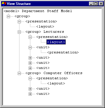
Figure 5.1 shows the structure of a departmental staff model. The following is an extract of the departmental staff model that shows the overall structure.
<model name="Department Staff Model">
<group>
<presentation>
<layout type="column" ySpacing="30" />
</presentation>
<group name="Lecturers">
<presentation>
<layout type="column" ySpacing="5" />
</presentation>
...
</group>
<group name="Computer Officers">
<presentation>
<layout type="column" ySpacing="5" />
</presentation>
...
</group>
</group>
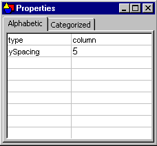
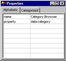
</model>The contents of the VDL tags can be displayed or hidden by expanding or contracting them. Clicking on a VDL tag selects it and displays the attribute names and values of the tag in the Properties window. Figure 5.1 shows that a layout tag has been selected and figure 5.2 shows its properties. The properties can be edited by changing the values in the Properties window.
Figure 5.2 – The properties window for the selected layout tag.
6. Creating a Tool Set
The tool set for a VDL model can be created by dragging and dropping tool icons from the Tools Palette onto a tool set window. A new tool set window is created with Edit>Create Tool Set. Figure 6.1a shows a tool set window after three tool icons have been dragged onto it. The browser input tool has been selected by clicking on it and its properties are displayed in the Properties window shown in figure 6.1b. The properties of the tools can be edited by changing the values in the Properties window.
Rules implement the behaviour of tools. A rule is created for a tool by double clicking the tool icon on the tool set window which will display the Rule Editor window described in the next section.
Figure 6.1 – Creating a tool set.
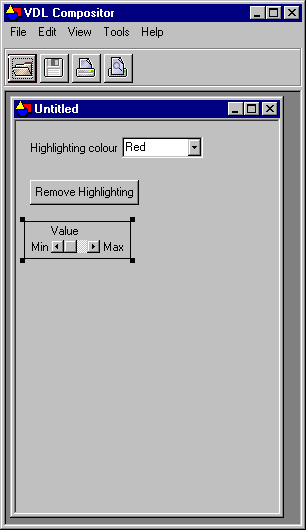
(a)
(b)
7. Creating and Editing Rules
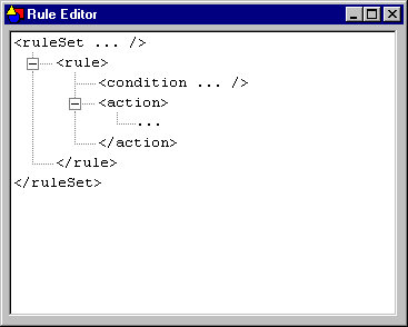
Rules are created and edited using the rule editor window. The rule editor window is displayed with Tools>Rule Editor and is shown in figure 7.1a. Figure 7.1a shows a new rule. The … marks indicate the parts of the rule that need to be edited to add the content.
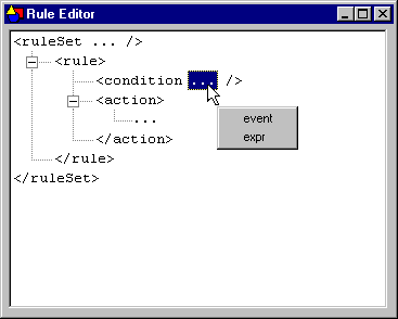
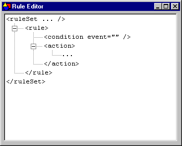
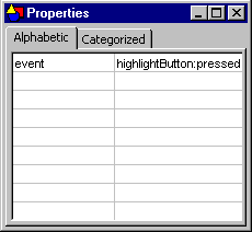
The parts of a rule are inserted by clicking on the … marks and selecting an option from the popup menu that will be displayed. Figure 7.1b shows the popup menu that enables the type of the condition to be inserted. Figure 7.1c shows the condition after the event attribute has been inserted. The name of the event is added by editing the event attribute in the Properties window (figure 7.1d). Figure 7.1e shows the condition after the name highlightButton:pressed has been added.
Figure 7.1 – Adding the event condition of a rule.
(a)
(b)
(c)
(d)
(e)
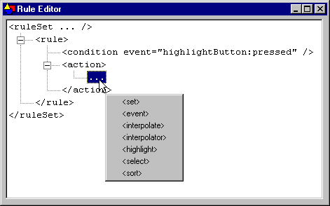
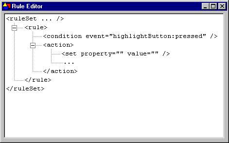
Messages are inserted into the action tags by clicking on the … marks inside the action tags. Figure 7.2a shows the popup menu that enables a message to be inserted. Figure 7.2b shows the rule after the set message has been added. The values of the property and value attributes are added by editing their values in the Properties window.
Figure 7.2 – Adding a set action to a rule.
(a)
(b)